Session 2: Digital logic primer
Now that we understand what we’re building and roughly how we’re going to do it, let’s dig into some of the fundamentals of digital design.
Binary arithmetic
The binary counting system, or base 2, is much like the decimal counting system we use everyday. As humans, we are no strangers to using a non-decimal counting system. We count our minutes and hours in the sexagesimal counting system, a notion which first originated with the ancient Sumerians. A counting system simply determines how we represent a number, and it is this binary representation that is particularly suitable for computer operations. That’s all there is to it!
The key ideas in binary arithmetic applicable to digital design are:
- There are two states: 1 and 0
- All numbers have an associated bit width. A 4-bit number holds 4 bits. The same is true in decimal but we often conveniently ignore this in basic arithmetic since this limitation is unimportant.
- When a number overflows (eg. the result of 1111 + 1), we roll back to 0. You can think of this as truncated addition, see below.
- 1 + 1 = 0 !
       2³  2²  2¹  2⁰
     ┌───┬───┬───┬───┐
       1   1   1   1    (15)
    +  0   0   0   1    (+1)
     ├───┼───┼───┼───┤
   1 │ 0 │ 0 │ 0 │ 0 │  (0, overflow!)
     └─┬─┴───┴───┴───┘
       │
       └─ Overflow bit (truncated)
Boolean functions
Boolean algebra is a close sister of binary counting, mainly because the 1 and 0 states map nicely onto true and false. True is commonly associated with 1 and false with 0. In boolean algebra, we define a few fundamental operations:
- AND: a.b
- OR: a+b
- XOR: a^b
- NOT: !a
There are a few more, but these are just negations of the above, like NAND !(a.b). I’ve been a bit careless with my syntax above, since I’ve tried to stick to the mathematical notation used for those operations. In software and HDLs, we use a slightly different mixture of symbols to represent the above.
For each operation, we can define a truth table. These enumerate the outputs for all the possible inputs. You’ll notice all operations save for NOT have 2 operands (inputs). Here’s the truth table for AND as an example:
A | B | A AND B
--|---|--------
0 | 0 |   0
0 | 1 |   0
1 | 0 |   0
1 | 1 |   1
Tip
Try and write out the truth tables for all boolean operations
Signed numbers
As computers started to proliferate, we needed a way to represent negative numbers. Remember, all we’ve got is 1s and 0s, you can’t just “add a -” to the start of the number. Eventually, we standardized on a method called two’s complement. There are three ideas we need to apply 2’s complement in our circuits:
- The most significant bit (ie. the leftmost bit) is the sign bit.
- If the sign bit is set, we subtract the number associated with that power of two from the remaining bits.
- To negate a number, we invert all the bits and add 1.
Let’s take an example:
  2³  2²  2¹  2⁰
┌───┬───┬───┬───┐
│ 1 │ 0 │ 0 │ 1 │
└───┴───┴───┴───┘
Interpreting this as an unsigned binary number, we’ve got 9 (8 + 1). If we interpret as signed, this becomes -8 + 1 = -7.
For negation, we have:
 2³  2²  2¹  2⁰
 0   1   1   1   Original: 7
 1   0   0   0   Inverted
 1   0   0   1   +1 = -7
What is digital logic?
Digital logic is an abstraction built upon fundamental units called logic gates. These gates are themselves made up of switching transistors arranged in special patterns with resistors to achieve the respective binary functions. There is no one strictly correct implementation of a gate, the “best” one will vary according to the specific power, area and performance requirements of the design. Here, we have a generic NOR and AND gate implementation:

The notion of digital is itself part of this transistor-level abstraction. Digital implies binary: 0 or 1, HIGH or LOW, 0V or 5V. However, MOSFETs or BJTs1 can take any allowed voltage within their rated values, which is inherently analog. So, to recap: gates are digital logic components themselves made of “analog” transistors. Of course, the transistors inside gates are chosen for properties that make them particularly suitable for gates, like their voltage transfer characteristics.
Digital logic won over analog logic for various reasons that mostly stem from the fact that having only two allowed states makes circuits easier to design and understand, and therefore lets us turn up the level of complexity of our circuits.
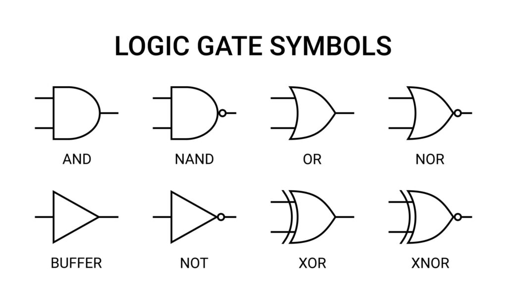
All logic gates implement one boolean function. These are circuits, after all, so it’s useful to have symbols for them:
You might imagine a simple logic function like (A AND B) OR NOT C can be
represented as such:
Tip
Feel free to mess about with the circuit above!
Combinational logic
Combinational logic is formed from boolean functions whose outputs are fully determined by their current inputs. You can achieve quite complex operations using just combinational logic and clever tricks to manipulate bits. These operations execute in zero time, ie. in under 1 clock cycle.
At the lowest level, combinational circuits are built from simple primitives such as NAND gates (in ASIC designs) or LUTs (in FPGA designs). We’ll get to these later; for now, you just need an awareness that how your logic functions are implemented will vary depending on the platform (ASIC or FPGA).
Note
Logic here means the collection of boolean functions that our circuit will implement. It can also refer to the gates, to the different digital components that you might build out of gates, to the HDL code you write and so on. It’s a general term for the thing that your circuit will do.
Karnaugh Maps
A word on Karnaugh maps…While the use of K-maps has mostly been relegated to the classroom and rarely appears in the real-world, it’s an invaluable tool for building intuition on logic reduction.
The main objective is to find the simplest circuit that can model our logic problem. It follows thus that the best solution has the fewest variables in the fewest terms. Recall that a K-map solution can be of the sum-of-products form or product-of-sum form, with the former involving collecting the largest groups of minterms and the latter the maxterms.
Sequential logic
So far, we’ve seen that we can evaluate arbitrary boolean functions using logic gates. However, any meaningful and useful computing system needs a bit more, in particular it needs to store previous values so it can use them in future computations.
The notion of ‘previous’ and ‘current’ require a concept of time. This is called synchronous logic. We say that our circuit is synchronous to a clock, ie. it responds to the clock, most commonly a rising edge (positive edge). A clock signal is a simple square wave with a 50% duty cycle. It is on for 50% of the period and off for the other half.
Tying this all together, we arrive at sequential logic circuits, where the outputs are a function of their current and previous inputs. Flip-flops, also called registers, are used to accomplish this. The simplest flop is a D-flip flop, as shown.

The component above has 3 inputs: clock, d and reset. It has one output q. A
D-flip flop holds the value of the previous input for one clock cycle. D-flip
flops are so common that we simply refer to them as ‘flops’.
Note
Sometimes, you get an additional output which is the inverted version of
Q, since it falls out naturally out of the transistor implementation of a D-flop.
Waveforms
One way to visualize sequential logic circuits is with waveform diagrams, also known as digital timing diagrams, as below.

On the 2nd positive edge of the clock, the input to the flop goes high. The output, however, remains unchanged. One clock cycle later, the flop’s output matches its previous input. Aha, we’ve got 1 cycle’s worth of “memory”!.
This diagram exposes a key understanding of synchronous logic: launching and
sampling/capturing. We say that d is launched on the 2nd clock edge but only
sampled by the flop on the 3rd positive edge. This diagram makes that a bit
clearer by drawing the 0->1 transition of d slightly after the positive edge.
In reality, things are more complicated.
Glossary
- Digital
- Describes a system in which the values are constrained to 1 or 0
- Analog
- Describes a system in which values can span a continuous range
- Logic gate
- An electronic component that implements a logic function
- (Boolean) logic
- A system of reasoning with two values, true and false, that uses operations like AND, OR to combine manipulate statements
- Binary
- Two. A counting system in which only two values are allowed: 1 and 0.
- 2’s complement:
- A way of expressing negative numbers in the binary counting system
-
Metal Oxide Field Effect Transistor, Bipolar Junction Transistor ↩